
DFT: Control Valves:
HI-100™ Severe Service Control Valve
 |
|
| Documentation: Product Specifications (145KB PDF) |  |
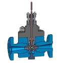
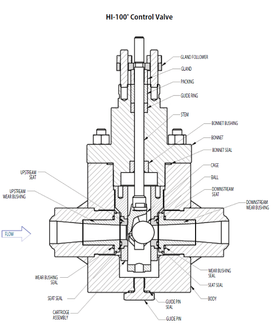
The HI-100 Control Valve features an in-line straight-thru venturi flow design.
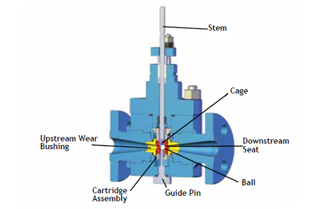
The control element, a spherical ball, is contained by a cage that positions it relative to the downstream seat by means of linear stem travel.
There are no close clearances between the moving parts (i.e. cage, ball and seat).These features enable the valve to operate smoothly and efficiently at high or low temperatures and/or in fluids carrying suspended particles such as slurries.
The Quick Change Trim feature permits in-line replacement of the internal trim (ball, stem, cage, seats, seat retainer cartridge and wear bushings).
Interchangeability of the upstream and downstream seats and wear bushings extends the life of the valve at no extra cost.
Class V shutoff is standard.
| Size NPS | 1/4 | 3/8 | 1/2 | 3/4 | 1 | 1-1/4 | 1-1/2 |
| Size DN | 8 | 10 | 15 | 20 | 25 | 32 | 40 |
| Cv (Kv) | 1 (0.9) | 2.5 (2.2) | 4.5 (3.9) | 10 (8.6) | 20 (17) | 31 (27) | 45 (39) |
| Size NPS | 2 | 2-1/2 | 3 | 4 | 6 | 8 | |
| Size DN | 50 | 65 | 80 | 100 | 150 | 200 | |
| Cv (Kv) | 80 (69) | 125 (108) | 180 (155) | 320 (275) | 720 (621) | 1280 (1103) | |
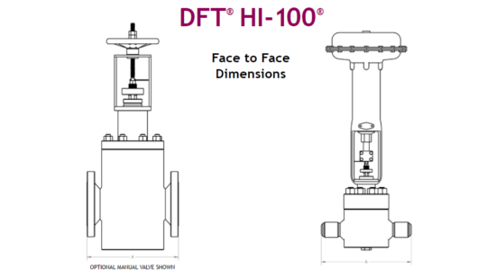
| Nominal Valve Size | ANSI Class 150 | ANSI Class 300 | ANSI Class 600 | ANSI Class 900 | ANSI Class 1500 | ANSI Class 2500 | |||||||
|---|---|---|---|---|---|---|---|---|---|---|---|---|---|
| NPS | DN | in | mm | in | mm | in | mm | in | mm | in | mm | in | mm |
| 1/4 | 8 | 4.00 | 102 | ||||||||||
| 3/8 | 10 | 4.00 | 102 | ||||||||||
| 1/2 | 15 | 4.25 | 108 | 6.00 | 152 | 6.50 | 165 | 8.50 | 216 | 8.50 | 216 | 10.38 | 264 |
| 1 | 25 | 5.00 | 127 | 8.00 | 203 | 8.50 | 216 | 10.00 | 254 | 10.00 | 254 | 12.12 | 308 |
| 1-1/4 | 32 | 5.50 | 140 | 8.50 | 216 | 9.00 | 229 | 11.00 | 279 | 11.00 | 279 | 13.75 | 349 |
| 1-1/2 | 40 | 6.50 | 165 | 9.00 | 229 | 9.50 | 241 | 12.00 | 305 | 12.00 | 305 | 15.12 | 384 |
| 2 | 50 | 8.00 | 203 | 10.50 | 267 | 11.50 | 292 | 14.50 | 368 | 14.50 | 368 | 17.75 | 451 |
| 2-1/2 | 65 | 8.50 | 216 | 11.50 | 292 | 13.00 | 330 | 16.50 | 419 | 16.50 | 419 | 20.00 | 508 |
| 3 | 80 | 9.50 | 241 | 12.50 | 318 | 14.00 | 345 | 158.00 | 381 | 18.50 | 470 | 22.75 | 578 |
| 4 | 100 | 11.50 | 292 | 14.00 | 356 | 17.00 | 432 | 18.00 | 457 | 21.50 | 546 | 26.50 | 673 |
| 6 | 150 | 16.00 | 406 | 17.50 | 445 | 22.00 | 559 | 24.00 | 610 | 27.72 | 705 | 36.00 | 914 |
| 8 | 200 | 19.50 | 495 | 22.00 | 559 | 26.00 | 660 | 29.00 | 737 | 32.75 | 832 | 40.25 | 1022 |
 | Hi 100 Control Valve
|
| DFT HI-100 MATERIALS OF CONSTRUCTION | |||
|---|---|---|---|
| Component | Carbon Steel | Alloy Steel | Stainless Steel |
| Body | A105 | A182 F22 or F11 | A479 316 |
| Bonnet / Bottom Cover | A105 | A182 F22 or F11 | A479 316 |
| Stem | 410SS Heat Treated & Hardened | 17-4PH | |
| Cage 1/4" to 2" | Stellite #6 | ||
| Cage 2-1/2" & Larger | Body Base Material w/ Stellite #6 Hardfacing | ||
| Cartridge | 316 SS | ||
| Guide Pin | A193 B7 | A193 B&M | |
| Gland | 303 SS | ||
| Follower | Carbon Steel | 316 SS | |
| TRIM STYLE | |||
| Standard | Feedwater | Steam | |
| Ball 1/4" to 4" | 440C | Ultra-Loy Ceramic | Stellite |
| Ball 6" and larger | Stellite | ||
| Seat 1/4" to 2" | 422 SS Heat Treated & Hardened | Stellite | |
| Seat 2-1/2" & Larger | 422 SS Heat Treated & Hardened | 316 SS/Stellite | |
| Wear Bushing | 422 SS Heat Treated & Hardened | 17-4PH | |
| SEALS | |||
| Low Temp 350 F Max (177 C Max) | High Temp 350 - 1000 F (177 - 538 C) | ||
| Packing | Teflon Chevron Style | Graphite | |
| Bonnet & Guide Pin Seal | Spiral Wound Gasket 304/Graphite | ||
| Seat Seal | Spiral Wound Gasket 304/Graphite | ||
| Wear Bushing Seal | Spiral Wound Gasket 304/Graphite | ||
| MANUAL VALVES | |||
| Yoke | Carbon Steel | Stainless Steel | |
| Handwheel | Cast Iron | ||
| Stem Nut | Bronze | ||
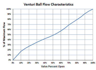 | DFT’s venturi-ball design is the only design that actually works with the physics of the fluid flow. Incoming flow enters through the nozzle to the control area. The smoothly converging nozzle lowers turbulence as theflow moves around the curved control path.Note that only rounded surfaces and conesare used for the control function. As the flowexits the valve, the diverging nozzle controlsexpansion and recovery so that no turbulenceis added to the flow stream.The preferred operating range of the valve isbetween 10% and 90% open. |
| Actuators | Actuator Accessories | Packing | Special Trim |
|---|---|---|---|
| Pneumatic Diaphragm | Air Filter Regulator | Graphite | Feedwater |
| Pneumatic Piston | Air Set | Teflon® (CVH) | Steam |
| Electric | Limit Switches | Live Loaded | Catalyst |
| Electro-Hydraulic | Manual Override | Emission Compliant | Slurry |
| Hydraulic | Positioner | ||
| Manual | Solenoid | ||
| Transducer | |||
| DFT CONTROL VALVE OPERATION | |
|---|---|
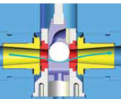
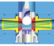
 | Closed Position: In the closed position, the ball is compressed into the conical seating surface by system pressure. Line contact between the ball and the seat loads the seating surface producing tight closure. As pressure increases, the seat load increases and the seal improves. During each valve stroke, the ball rotates and repositions itself presenting a new sealing surface to the seat, prolonging the tight shutoff capability. Temperature changes do not affect the tight shutoff since there is freedom of movement between the ball and the seat. The ball cannot become wedged into the seat. The guide pin is used to set the valve position, but has no function during normal operations. |
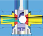
 | Full Open Position: In the full open position a straight-thru flowpath exists and the valve operates with the inherently high flow capacity of a venturi. The ball is mechanically held out of the flow stream by four inclined pads on the cage which oppose the pressure differential force. The Bernoulli effect moves the suspended particles towards the center of the fluid stream, preventing them from settling out into the body. This keeps the valve clean and free of material deposits in all positions during the valve stroke. |
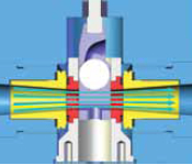
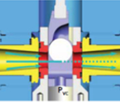
 | Close Throttling Position: As the valve opens, it operates in the close throttling position. In this position, the ball is supported by the two forward inclined pads on the cage and the seat surface which oppose the pressure differential force caused by the Bernoulli effect. The ball is supported and stable throughout the valve stroke and does not pinwheel or chatter. |
 | Intermediate Throttling Position In the intermediate throttling position, the ball rests on the four cage pads and is opposed by the same differential pressure force. The stable suspension of the ball throughout the valve stroke permits extremely close and repeatable control throughout the entire valve stroke. |
| THE BERNOULLI PRINCIPLE | |
|---|---|
Energy per unit volume at inlet = Energy per unit volume at outlet The best example of the Bernoulli Principle is often called the Bernoulli Effect which states that fluid pressure decreases as fluid velocity increases. | |
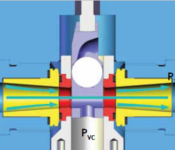 | The illustration shows the typical change in pressure as the fluid moves through the valve. At inlet, the pressure is P1. Velocity increases through the valve to a maximum as it moves through the valve port. At the valve port, the pressure drops to Pvc (pressure at the vena contracta), which is the lowest pressure in the valve. As the fluid exits the valve, pressure recovers to P2 which is lower than P1. |
 | Cavitation Control At P1 the fluid stream is all liquid. Liquid flashes at the valve port when the pressure at the vena contracta (PVC) drops below the liquid vapor pressure. As the velocity decreases in the exit nozzle, the pressure increases (or recovers) to P2 and the vapor bubbles collapse. This is known as the potentially damaging phenomena called cavitation. Unlike tortuous path valves, our control valves manage cavitation. Bubbles form at the lowest pressure (highest velocity) which is at the center of the fluid stream. The subsequent collapse is within the hydraulic barrier, not on metal surfaces. Our nozzle design provides a smooth recovery prior to the fluid exiting the valve. |
- ANSI B16.5
- Pipe Flanges & Flanged Fittings
- ANSI B16.10
- Face to Face & End to End Dimensions of Valves
- ANSI B16.34
- Valves – Flanged, Threaded & Welding Ends
- ANSI/FCI 70-2
- Control Valve Seat Leakage – HI-100® & Ultra-Trol® seat test
- ANSI/ISA 75.01
- Flow Equations for Sizing Control Valves
- ANSI/ISA 75.08.01
- Face-to-Face Dimensions for Flanged Globe-Style Control Valve Bodies - LSV-100™
- API 598
- Valve Inspection & Testing – Uniflo® seat test
- MSS-SP 25
- Standard Marking System for Valves, Fittings, Flanges & Unions
Codes and Standards:
- Straight-thru Design solves your performance problems
- Eliminates Damage: Our unique nozzle design smooths turbulence which eliminates body, trim and piping damage caused by high velocity fluid impingement in your system.
- Handles Greater Flow: Since we have no tortuous path through our valve, our valves have a higher Cv than that of the same size valve made by competitors, often saving you money.
- Precision Modulation & Control: Our 200:1 turndown ratio and linear flow characteristic gives you precise control over the entire operating range.
- Unique Trim Design lowers your cost of ownership
- In-Line Repair: All styles can be repaired in-line without the need for expensive special tools saving you time and money.
- Long Life: Our trim design uses wear components at the critical places along the flow path maximizing design life for the application.
- Low Replacement Costs: Our unique ball, cage and wear bushing design allows you the flexibility to replace only the worn parts, lowering your cost of repair significantly when compared to our competition.
- Wide Application Range can be used in nearly any service
- ANSI 150 to 4500: Handles all ANSI applications, pressures up to 16,000psi and temperatures from -425°F to 1900°F.
- Liquid, Gas, Steam, Slurry: Our non-tortuous path design handles liquids, gases, steam (including mixed phase flow), abrasives and many slurry applications.
- Materials: Standard body materials are Carbon, Alloy and Stainless Steel. High nickel and exotic alloys are also available – any weld-able alloy that is available as a forged material can be used.
- Venturi Nozzle Design reduces turbulence in your piping system
- Cavitation Control:Our nozzle design controls cavitation and reduces the associated noise and vibration.
- Particulate and Mixed Phase Flow: Our nozzle design moves particles and water droplets to the middle of the flowstream avoiding costly damage.
- Prevents Erosion: Our nozzle design smooths the flow and reduces the potential for valve body and pipe erosion.
- Petrochemical
- Heavy Oil Upgrading
- Drum Level Control
- Refinery
- Abrasive Slurry Control
- Amine Service
- Butadiene
- DEA
- Pipeline
- Gas Plant Pigging
- Pipeline Control
- Pulp & Paper
- Powerhouse
- Steam Control
- Steel
- Powerhouse
- Aerospace
- Air
- Fuel Oil
- Gas
- High Pressure Water with fines
- Methane Vapor
- Chemical
- Abrasive Slurry Control
- Hot Hydrogen Gas
- Pitch Blend Control
- Powerhouse Applications
- Super Critical Water Oxidation
- Government/
Military Test - Air
- Cryogenic
- Nitrogen Gas
- Steam
- High Pressure Water
- Power
- Bottom Ash
- Condensate Drain
- Drum Emergency Blowdown
- Drum Level Control
- Feedwater Control
- Feedwater Recirculation
- Fuel Oil Control
- Geothermal Water Injection
- Power Operated Relief
- Soot Blower Control
- Spray Control
- Steam PRV
- Thermal Drain
- Turbine Bypass
- Turbine Steam Extraction